Filter material
The following requirements must be met by an ideal filter medium:
- Dimensional and chemical stability as well as the highest temperature stability possible.
- Bending and tensile strength so no damage occurs from mechanical motion during cleaning.
- Optimal air permeability together with the highest possible retention of extremely fine dust.
| Type of filter material | Forms | Application |
|---|---|---|
| Fabric |
|
|
| Needle nonwoven |
| |
| Nonwoven |
|
|
| Sintered filter elements |
|
|
| Plastic fibre |
|
|
| Glass fibres |
|
|
| Ceramic fibres |
|
|
| Natural fibres |
|
|
| Metallic fibres |
|
|
Technical data of filter media
(according to VDI guideline 3677 and VDI guideline depth filter)
| Fibre type | Short mark | Permanent temperature* °C dry (short-term**) | Hydrolysis | Acids | Alkalis | Oxidants | Organic solvents |
|---|---|---|---|---|---|---|---|
| Cotton | CO | 75 (80) | - | - | + | 0 | + |
| Wool | WO | 70 (80) | - | + | - | 0 | ++ |
| Polyester | PES | 135-150 (150) | - | 0 | 0 | + | + |
| Polypropylene | PP | 90 (95) | ++ | ++ | ++ | - | 0 |
| Temperature resistent Olefin (Trol) | RO | 125 (130) | ++ | ++ | ++ | - | 0 |
| Homopolymer Polyacrylnitrile | PAN | 125 (135) | + | + | + | + | + |
| Polyamide | PA | 110 (115) | 0 | 0 | + | 0 | + |
| Polyphenylene sulphideulfid (Ryton) | PPS | 160-190 (200) | ++ | ++ | ++ | - | + |
| Polyimide (P84) | PI | 200-240 (260) | + | 0 | 0 | + | + |
| Meta-Aramid (Nomex) | NO, NX | 180 (200) | 0 | 0 | 0 | 0 | + |
| Polytetra fluorethylene | PTFE | 250 (280) | ++ | ++ | ++ | ++ | ++ |
| Glass | GF | 260 | + | + | 0 | ++ | ++ |
* An individual examination on the respective substances is absolutely necessary
** Depending on the process, deviations are possible
++ very good ¦ + good ¦ 0 satisfying ¦ - bad
Manufacture of filter materials
Filter materials are used to manufacture filter bags, filter pockets, filter cartridges, pleated filters, and filter cassettes. They are either sewn, welded, glued or cast together.
The seams can be sealed, if necessary. The bases and sealing units on the head are either sewn in or moulded on for plastic versions. The options for sealing the filter bags to the base plate are:
- Sewn-in double-bead snap ring
- Sewn-in ring
- Sewn-on gasket
- Cast-on frame with profile seal
Design of cleanable filter cassettes for suspended matters (HEPA filter)
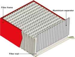
Today, the most common design of cleanable filter cassettes exists of a meander formed folded filter medium, which single layers are hold on distance by separators. The resulting filter media package is finally casted with a frame and the bottom is equipped with an elastic gasket.
A variety of material alternatives is available for each individual component:
- Filter medium: Laminated micro-fibreglass fleece*, synthetic fleece with PTFE membrane
- Spacer: aluminium*, stainless steel, plastics
- Casting compound: polyurethane*, silicone
- Frame: MDF*, galvanised steel, stainless steel
- Gasket: EPDM*, silicone
*most common standard
Main difference to non-cleanable cassette filters:
Non-cleanable HEPA cassette filter are exclusively equipped with unreinforced, low-cost micro-fibreglass fleece. They are not capable to withstand a cleaning surge with pressurized air. Unfortunately, the difference is only visible for experts. That's why Infastaub uses almost exclusively filter cassettes with cleanable filter media.
Another reason was in the past to install within a two-stage cleanable HEPA-filter the cassette of the second filter stage in the first filter stage. The amount of filter cassettes to be disposed could be reduced through this. Today, the filter change is usually realized with safe-change, so that this option is not possible.
Design of filter cartridges
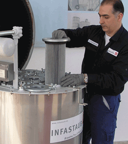
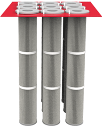
Filter cartridges consist of pleated filter media, which are brought into a round or oval shape. In order to prevent a collaps of this star-shaped ring, bigger cartridges also have a supporting cage. Depending on the design, this supporting cage is casted with the filter head and filter bottom. Alternatively it can be loosely inserted. The design of this downstream filter head is extremely versatile. Besides the often simple ring design, several versions are available: screw-retained bayonet flange, screwed header flange and further types for a filter change from the clean gas or raw gas side.
The conventional cartridge filter medium is a polyester spunbonded fabric. However, a great amount of other plastic fibre are alternatively available. The filter media can be specially treated depending on the application. For this purpose e. g. antistatic, oleophobic, hydrophobic, nonadhesive or suitable for particulate matters are available. Another alternative are filter media made of stainless steel.
In the meantime cartridge filters exist in filter classes ePM10 50% (F7) up to filter classe H13.
Depending on the external diameter of a cartridge, the cleaning behaviour is influenced by the fold depth and the fold number per circumference (tip distance). Both factors have a direct influence on the installed filter surface and cleanability. Here, the it is necessary to choose the factors in such a way, that an optimum process solution is reached.
The cartridge length though has only a small influence on the cleaning behaviour. However, special reinforcements at the circumference are necessary for longer lengths in order to keep the cartridges stable in shape. Lengths up to 2 m are common.
Design of pleated element filter
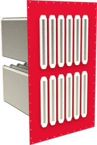
Pleated element filter are made of pleated filter media. Contrary to a catridge they aren't in a round shape, but arranged flatly. In order to prevent a collapse of the plate-shaped media packages, they are either adhered together point to point or either fixed with suitable interior components.
The filter medium is casted with the filter head and filter botton. The filter head equipped with a gasket arranged on clean or raw gas side.
This filter design hasmostly the same filter classes, filter media and filter media characteristics like with filter cartridges. The same applies to the cleaning behaviour which can be influenced by the fold depth and fold number (tip distance).
The length of a pleated filter element is limited due to the relatively narrow interior channels. (The effect of a pneumatic cleaning impuls is reduced above a certain length ).
A variety of material alternatives are available for the individual elements:
- Filter medium: Rigid plastic non-wovens or rigid needle felts
- Casting compound: polyurethane*, silicone
- Side bar: GFK*, stainless steel (Infastaub)
- Gasket: EPDM*, silicone
*most common standard
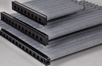
Design of sintered plastic filter
Sintered plastic filter are either produced plate-shaped like a pleated element filter out of profiled sintered plastic or in a round shape. In both cases the filter elements must adhered with a closed bottom and a downstream head part.
Infastaub uses round shaped sinter filters with a PTFE membrane which are preferably arranged in parallel - similar to a pleated element filter.
The length of a pleated filter element is limited due to the relatively narrow interior channels.
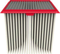
Design of multipocket filter (shaker filter)
Multipocket filters have a majority of single filter pockets, which are sewn together to a greater package in the area of the filter outlet. Because of this reason, woven filter facrics are usually used. The sewn single pocket receive a joint sealing frame, which is braced on the sealing surface of the filter unit. Similar to a bag filter or pocket filter, a collapse of the filter pockets is prevented with a supporting frame.
Design of pocket filter (jet filter)
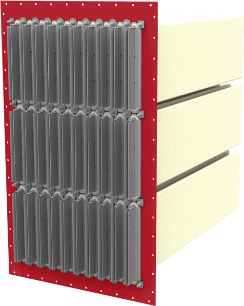
Filter pockets are made of needle felt which is sewn to a flat, elongated sack. One side of the filter pocket is sealed with a stable longitudinal seam. The other open side (clean gas outlet) is equipped with integral sealing bead. In order to avoid a collaps of the filter pocket during operating, the filter pockets are pulled on a supporting frame, similar as with bag filters. The sealing bead of the pocket is than placed in the head of the supporting frame. By pressing the head of the supporting frame, the pocket filter is tensed by a support plate on a sealing surface of the filter unit.
The gas flow is from outside to inside. All plastic fibre felts can be used as filter media. They are cleaned by jet pulse.
Raw gas side filter change
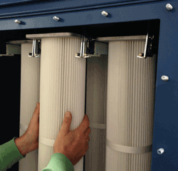
Changing of filters is carried out from the raw gas side. For this, appropriate maintenance openings are available on the raw gas side. The service staff grabs through this opening in order to reache the dusty filter elements to be changed. A tool-free filter change should be considered with a filter change from raw gas side.
This kind of filter change is ranked as very dusty.
It is specially used for filter units with vertical installed filter elements, which have not enough height above the unit for filter change or because of safety reasons, e. g. unsecured assembly at great height.
Clean gas side filter change
For this filter change the filter element is pulled out of the raw gas area into the clean gas area (or directly exterior) through a sealing plate. This applies to almost all kinds of filter elements. Cassette filters are an exception, because the entire filter body is already arranged clean gas sided. Overall, sealing of the filter elements is arranged clean gas sided in all cases.
During filter media change the service staffs works at the clean gas side, so that also non tool-free fastening systems can be used.
Nevertheless, dissolving dust from the filter causes though that this principle is only less dusty than a raw gas sided filter change.
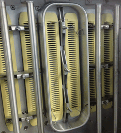
Bag in Bag (BIBO) filter change
A special change collar is mounted on the clean gas side for the change of filter elements. A waste bag is fixed on this change collar in order to pull out the dusty filter element into the bag without emitting any dust to the surrounding. After removal of the now sacked, used filter element the new filter element can be mounted. Afterwards the used change collar is positioned in front of the next filter.
Since the change collar is mounted in front of the opening of the filter element, the here mounted cleaning system needs to be removed in advance. They need to be removed specially for bag filters with reusable supporting cages.
Filter changes ususally are carried out after a dust blow-out. Then the clean gas chamber is already dusted in the beginning of the filter change. The "bag in bag" - or also "bag in bag out" filter change is therefore not at all a dustless kind of filter change. It is just less dusty.
The term BIBO is wrongly considered to be a safe-change filter change. This is not appropriate because the bag in bag change has no permanent barrier to the clean gas area.
First Rinse – Filter wetting
Spray nozzles are permanently arranged on the raw and clean gas side. With them, the entire interior of the filter is wetted, so that the dust is not only layered on the filter element.
The dust exposition of service staff is hereby during filter change significantly reduced. But since wetting is not a cleaning (neither CIP nor WIP), the following aspects should be taken into acount in the assessment:
- Unsufficient saturation of the filter cake might be possible
- Wetting is carried out once in the beginning of filter change. Bigger filter units might already have again dried dust during filter change. This process is certainly possible with thin dust layers or warm surfaces.
- Touching of the wet filter cake (might be muddy), which is builded up on the filter surface. The situation is not better in case there is no tool-free filter change
- At the end of filter disassembly the entire filter interior needs to be thoroughly cleaned. The The remaining "mud" deposits in the interior could otherwise bother the entire process after re-commissioning. Remaining dust surfaces can also dry during this work.
- This is applies for additional use of a safe-change frame
- Larger volume of mud can arise, which needs to be cost-intensively recycled
Safe-Change filter change
In terms of filter containment, the safe-change system is a barrier between user and production area. It is a so-called Restricted Access Barrier System (RABS). Depending on the used closure system of the protection system and design of the changing collar, containment level up to OEB 5 are possible.
A specially formed filter change frame is mounted permanently in front of each filter element. Preferrably, a frame shall be used, where the utilized fixing ring can be positively fixed all round to the greatest possible extent. (Simple beadings haven't poved to be effective, because the changing back is fixed unsufficiently.) Furthermor, the frame needs to have two independend holding positions for two o-rings.
In order to use at best the features of the safe-change system, the used plastic sac is mounted to the changing frame even during filter operating. By using plastic foil sacks, this principle is limited to operating temperatures of max. 130 °C. Above this temperature the changing sack can't remain at the filter system and the barriere function in the means of RAPS is elimnated.
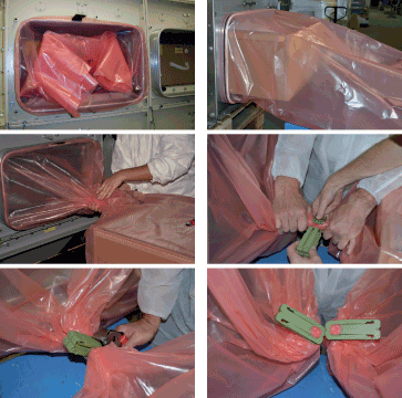
A safe-change filter change is carried out as following:
- The filter element to be changed is pulled into the protection sack.
- The protection sac is closed between changing frame and filter element with an appropriate closing system. Afterwards it is separated in the area of the closing zone, so the cut-off points are closed dustfree on both sides. (tear sealing, staple system, or others)
- The new filter element is packed in a new sack which is connected to the change collar.
- Only now the waste sac still mounted to the collar is detached und moved within the new changing sac around the new filter. This way, the rest sack as well as the sealing ring is situated at the sack end of the new sack.
- Now the new filter can be installed.
- Finally, the new sack including waste sack is rolled togehter in connected status and the filter door is closed.
A safe change is carried out as follows:
- The filter element to be changed is pulled into the protection bag
- The protection bag is closed between changing collar and filter element by an appropriate closure system.
- Afterwards it is separated in the area of the closing zone, so the separating points are closed dustfree on both sides.
- The new filter element is packed in a new sack which is connected at the changing collar.
- Only now the still remaining sack mounted at the changing collar is unfastened.
- The new filter can now be installed.
- Finally, the new sack including the remaining sack is rolled together and the filter door can be closed.
Filter differential pressure monitoring
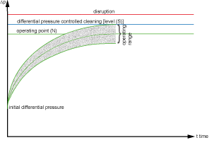
A differential pressure monitoring is very informative and important for the procedural function monitoring. It is comparable to the tachometer in a car. The differential pressure of a new, dustless filter element is very low and increases ver fast at cleanable filters with a time-based cleaning. It should approximate to an almost constant operating point N. During the entire lifetime of a filter, the value usually increases then very slow, until a defined end differential pressure is reached. High differential pressures result in an increased energy consumption of the fan and depending on the fan control to reduced suction velocities.
A differential pressure value that is to high or to low shows only very seldom a malfuntion of the filter.
The initial differential pressures are depending on velocity, filter media and design. This applies unavoidably to the filter operating point and the end differential pressure, whereas the dust properties and the process to be exhausted have an important influence.
Differential pressure cleaning
Level, which starts the filter cleaning with a differential pressure controlled cleaning.
This values needs to be chosen with a certain distance above the very process-depending operating point N, in order to consider the long-tem increase of the process-depending operating point N. It is possible over the lifetime of filter elements that this value needs to adjusted.
Further aspects are:
- With filter systems that need a filter cake for optimum operating, this value must always be so hieh, that this is always possible.
- Vaues to high cause an unnessary high energy consumption.
- Values to low under the operating point N cause a permanent cleaning which might result in a premature filter damage.
Max. differential pressure (malfunction)
Terminating a maximum differential pressure value of a filter element, that causes a filter change, should be carried out in consideration fo following points:
- Uneconomic operating cause increased energy consumption
- Unsufficient air velocity
- Differential pressure must be far below the bursting pressure of the filter elements
In some processes the filter differential pressure increases at lifetime end not only very slow, but exponential. There is a danger of a sudden production downtime then. To minimize this risk, an additional pre-alarm point can be defined.
Min. Differential pressure monitoring (Filter rupture monitoring)
This seldom used monitoring is based on the assumption that a bigger filter rupture leads to a very considerable differential pressure drop of a filter stage.
On the one hand this threshold value must be chosen so low that usual differential pressure variations, e. g. because of turndown or compartmentalisations of single pipline elements, are disregarded. On the other hand the threshold value must me chosen close to the operation point of filter elements, in order to recognize the differential pressure drop.
Considering that usual differential pressure variations are possible when a single filter element within filterstages with a great number of elements is missing and only bag filters and pocket filters have a significant differential pressure drop at all in case of a bigger filter leak, this kind of monitoring should be replaced by more appropriate methods.
Filter leakage monitoring
Manual test of particulate matter cassette filter for control of leak-proof of the filter seal on the sealing surface, this means the test happens in an installed condition. For this purpose either a specical gasket or a profiled sealing surface is used. The accuring hollow is pressure checked to a defined pressure. The resulting remaining quantity is measured. When the remaining quantity is below a defined value, the seal system is tight.
This test only varifies the sealing on the filter surface. Possible leakages, e. g. between sealing and cassette frame (filter frame) are not recognised, not to mention filter leaks. Thats why these tests are seldom used and so-called filter efficiency tests apply.
Residual dust monitoring discontinuous
Usually the residual dust monitoring is a gravimetric measurement.
A partial flow of the exhaust gas is directed to a sampling filter. Since as well the entire exhaust volume flow as the sampling volume flow are familiar, the dust concentration of the exhaust gas can be calculated by the increase in weight of the sampling filter.
A chemical analysis also determine the particular fractions.
Residual dust monitoring continuous
Tribo-electrical dust concentration measuring
Dust particle, that come in contact with a sensor, discharge very small electric loads to the sensor, which can be redirected. Thus, the electric current can be measured. When having constant circumstances, there is a linear relation between the current signal and the dust concentration. Tribo-electrical measuring instruments are used for a quality dust measurement (limit values) and with restrictions for the quantitative dust measurement (determination of dust load). (source: Leitfaden zur Emissionsüberwachung – Bundesministerium für Umwelt, Naturschutz und Reaktorsicherheit)
Advantages compared to an optical measurement are amongst others: high degree of accuracy (suitablity for very low dust concentration), minimum operating costs (no purging air necessary) and service friendliness (very low influence on contamination of the sensor on the measuring results).
Visual measuring of dust concentration according to the scattered light method
A light beam penetrates the dustladen exhaust air in a defined section, e. g. stack, pipe or channel. Thereby, it recognizes a weakening depending on the dust load as a result of absorption and scatter on particles. This weakening serves as dust measurand. (source: Leitfaden zur Emissionsüberwachung – Bundesministerium für Umwelt, Naturschutz und Reaktorsicherheit)
Since light source, reflectors and sensors would gather dust very quick, the relevant components are contiuously cleaned with a purge gas flow. Additionaly, regular service intervals are necessary in order to receive qulified measuring results.
Filter leak monitoring with simultaneous retention of residual dust
A special form of a filter leak monitoring can be interesting for dusts hazardous to health, speciall when a second filter stage is wanted or needed.
Depending on the filter class, the second filter stage (police filter) can only serve as dust retention in case of a filter rupture. When using higher filter classes, an improvement of the residual dust value is possible at the same time.
With a simple electrical differential pressure monitoring of the police filter, a continuous filter monitoring of the first filter stage is possible.
DEHS / DOP filter test
Validation of the separation grade of particulate matter filters (EN 1822-1). Thus, every single filter element (as from filter class H13) is tested at nominal volume flow using the test aerosol di-octylphthalate respectively di-ethylhexylsebacate. The particle size is within the area of "Most penetrating particle size" (MPPS) around 0,1 to 0,3 µm.
To conduct this test, the respective test aerosol, which is generated by a special aerosol generator, should be directed regularly to the gas volume flow. The aerosol concentration has to be measured before and after the filter using a particle counter. The quotient of both values provides the actual separation grade of the filter elements. Depending on the measuring equipment either only integrale mean values can be realised or also filter scans.
In order to realise the test, device-specific and metrological requirements have to be taken into account already when designing the filter system:
- An individual test of each filter needs to be possible
- Also smallest leakages within the clean gas area have to be avoided (this includes also threads of smallest screw connections)
- Creation of appropriate measuring points before and after filter elements. Thus, pre-installed feed and measuring lances are used as well as terminal ports (usually bigger Tri-Clamp or threaded couplings) for including of measuring systems
The application of an integrated scan test equipment is a special kind of this filter test. This scan test resembles the test of the producer and determines not only the integrale average value of the filter efficiency, but also the local filter efficiency of every single point within a filter cassette. This permanently installed device is extremely complex and only used for special applications, e. g. high-security laboratory.
